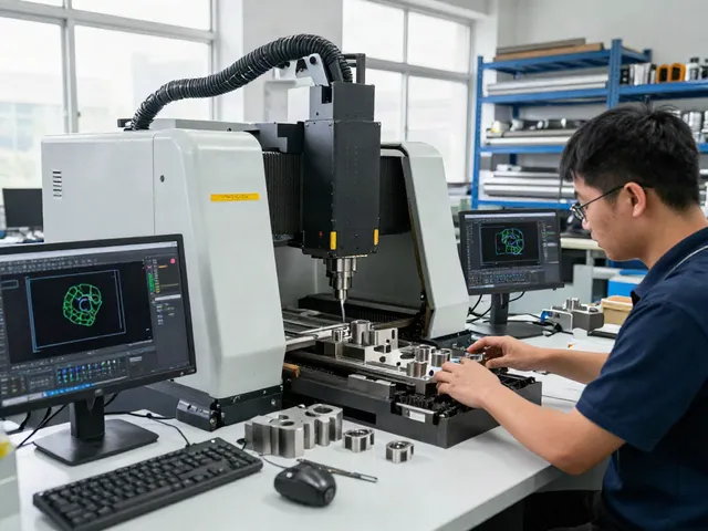
Understanding Plant 3D Isometrics
What are Plant 3D Isometrics?
Plant 3D isometrics are fundamental engineering drawings used in plant design to provide a three-dimensional representation of piping systems. Unlike traditional 2D drawings, isometric drawings convey complex information about the arrangement and dimensions of pipelines, valves, and fittings in a way that is easily interpretable. Their ability to illustrate the spatial relationships between various components makes them an invaluable tool in the development of production plans, construction, and maintenance strategies. For those venturing into the realm of isometric design, a strong grasp of Plant 3D isometrics can significantly enhance their workflow efficiency.
Importance of Isometric Drawings in Engineering
Isometric drawings play a crucial role in engineering by enabling clearer communication of design intent. They allow engineers, architects, and construction teams to visualize how components interact within a 3D space, bridging the gap between different engineering disciplines. This is especially useful in projects involving multiple contractors and teams since isometric representations are universally understood, reducing the likelihood of misinterpretation. Moreover, these drawings also serve as a guide for fabrication and installation, thus ensuring quality and compliance with standards throughout the execution phase.
Common Applications of Plant 3D Isometrics
Plant 3D isometrics find application across various engineering fields including chemical, oil and gas, and water treatment. In the chemical industry, they are used to illustrate piping systems, helping engineers design systems that minimize the risk of leaks and ensure safe operation. In oil and gas, isometric drawings are vital for planning pipelines and facilities, where understanding the spatial configuration is critical for both safety and efficiency. Water treatment facilities also utilize these drawings to plan and execute the installation of complex piping systems, ensuring a smooth flow of operations.
Creating Effective Isometric Drawings
Step-by-Step Guide to Drawing Isometrics
Creating effective isometric drawings involves several key steps:
- Gather Requirements: Understand the project specifications and gather all necessary data.
- Define the Layout: Outline the base plan, indicating major components, flow directions, and critical dimensions.
- Choose Scales: Establish a suitable scale for the isometric representation to maintain clarity.
- Add Components: Incorporate pipes, valves, and other fittings into the layout, ensuring correct proportions and orientations.
- Dimension Accurately: Include dimensions in three directions to assist with fabrication and installation.
- Review and Revise: Conduct a thorough review to check for compliance with standards and rectify any discrepancies.
Tools Required for Effective Isometric Creation
A variety of tools are essential for effective isometric drawing creation:
- Software: Programs like AutoCAD Plant 3D are specifically designed for generating isometric drawings and integrating 3D modeling.
- Templates: Use standardized templates to ensure uniformity across all isometric drawings.
- Measuring Instruments: Digital measuring tools can aid in maintaining accuracy when transferring dimensions.
- Reference Material: Standard reference guides are useful for understanding substance properties and required symbols.
Common Mistakes to Avoid in Isometric Drawings
While creating isometric drawings, engineers should be aware of common pitfalls:
- Ignoring Scale: Failing to maintain scale can lead to misleading interpretations of the drawing.
- Omitting Dimensions: Neglecting to add essential dimensions can result in fabrication issues later down the line.
- Misrepresentation of Components: Misplacing symbols or misrepresenting component orientations can greatly affect project outcomes.
- Overcomplicating Designs: Adding unnecessary complexity can cloud clarity; simplicity is often more effective.
Advanced Configuration Techniques
Configuring Settings for Precision in Isometrics
Precision in isometric drawing configuration is paramount. Users can enhance their output by carefully configuring settings:
- Adjusting Angles: Fine-tune angle settings to properly represent the 3D space.
- Defining Line Types: Use different line types to distinguish between pipes, fittings, and annotations.
- Establishing Units: Ensure that the drawing units are consistent throughout to avoid confusion.
Integrating Isometric Symbols for Clarity
Incorporating standard symbols enhances the clarity of your isometric drawings. Using recognized symbols for valves, fittings, and other components minimizes misinterpretations and helps communicate crucial information effectively. Ensure to adhere to industry standards to bolster understanding across all stakeholders involved in the project.
Utilizing External Resources for Enhanced Output
External resources such as libraries of standard components, configuration templates, and expert guides can significantly improve the output of your isometric drawings. Many software platforms also provide add-ons that can help refine your isometric models quickly, allowing you to leverage existing knowledge for better efficiency and accuracy.
Best Practices for Engineers
Standardizing Your Isometric Designs
Standardization in isometric design fosters consistency across projects. Develop templates that encompass common layouts and components, making it easier for engineers to adhere to a cohesive format. This practice not only streamlines the design process but also aids in reducing errors and inconsistencies in documentation.
Collaborating with Teams on Isometric Projects
Collaboration tools are invaluable when working on isometric projects involving multiple teams. Use cloud-based software solutions that allow real-time editing and sharing of isometric drawings. This transparency ensures that any changes are immediately visible, facilitating better communication and reducing the chances of misalignment among teams.
Staying Updated with Industry Standards
The field of engineering is constantly evolving, and staying updated with industry standards is vital. Regularly review publications, attend workshops, and engage in professional organizations that focus on plant design and isometric drawing standards. This proactive approach not only enhances your knowledge but also ensures that your designs remain compliant and relevant.
FAQs about Plant 3D Isometrics
What software is best for creating Plant 3D isometrics?
The primary software for creating Plant 3D isometrics is AutoCAD Plant 3D, designed specifically for this purpose.
How can I improve my isometric drawing skills?
Practice regularly, use tutorials, and study examples of professional isometric drawings to refine your skills.
What are the key components of isometric drawings?
Key components include pipes, fittings, valves, and annotations that represent different elements in a simplified view.
Can isometric drawings be used for project management?
Yes, they provide clear visual references that aid in understanding complex projects, facilitating better communication.
Is there a difference between isometric and orthographic drawings?
Yes, isometric drawings represent three dimensions in a single view, while orthographic drawings show multiple views of the object.